I see one problem with your configuration
for axis channels 1 and 2. But axis channel 0 should work properly.
The issue is that some type of axes modes require 2 output channels to be
configured (both Output Chan0 and Output Chan1). Step/Dir axes are
simpler in that they only need one output device to be configured – which
Step/Dir generator to use. So only Output Chan0 is used (Output Chan1 is
a don’t care and can be set to any value). So in the 3 axis
channels that you have configured as:
Axis Chan0 – Output Chan0 = 0 (use
step/dir generator #0)
Axis Chan1 – Output Chan0 = 2 (use
step/dir generator #2)
Axis Chan2 – Output Chan0 = 4 (use
step/dir generator #4)
Should be:
Axis Chan0 – Output Chan0 = 0 (use
step/dir generator #0)
Axis Chan1 – Output Chan0 = 1 (use
step/dir generator #1)
Axis Chan2 – Output Chan0 = 2 (use
step/dir generator #2)
But this doesn’t explain why your
axis 0 isn’t working. What are you commanding and what happens?
If you press “Move” on the
Step Response Screen: The screen parameters and configuration settings
will be downloaded to the board, the axis will be enabled, and a movement of
the specified size should occur. Do this and watch the Axis Screen.
Does the axis become enabled? Does the commanded Destination change as if
the motion is occurring? If so but no motor motion, the problem is
probably a wiring or compatibility issue with your drives.
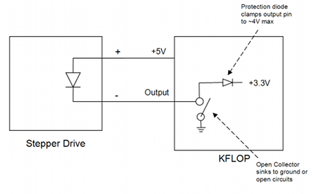
When you select Step/Dir Output channels
0-7 the Step/Dir generator output pins operate in “Open Collector”
mode. In this mode the output pins basically switch between being shorted
to ground and open circuit. This mode is useful to allow the 3.3V outputs
to drive +5V optos where the LED anode is connected to +5V. When the
output shorts to ground, the opto “sees” +5V and turns on.
When the output “open circuits” the LED turns off. (In
reality the output pin has an ESD protection diode that is connected to the
3.3V supply, so the open circuit is only allowed to float to a maximum of ~4V
and the opto diode will still “see” ~1V. Most all LED’s
require more than 1V to turn on).
To test this mode with a voltmeter or
oscilloscope: Cycle power on KFlop so that it is in the default
configuration. Using the Digital I/O screen check and uncheck the
checkbox in the “Output” column while the checkbox in the
“State” column is unchecked. Note that if no pull-up source
is connected to an Open Collector output the pin will remain at ~0V regardless
of whether it is driving to ground or open circuit.
To have the Step/Dir generators drive TTL
style outputs add 8 to the output channel (specifying output chan0=8 will still
drive step/dir generator #0 but in TTL output drive mode instead). TTL
output mode will basically switch the output pin from being connected to either
ground or +3.3V.
To test this mode with a voltmeter or
oscilloscope: Cycle power on KFlop so that it is in the default
configuration. Using the Digital I/O screen check the checkbox in the
“Output” column then check and uncheck the checkbox in the
“State” column. The output should be observed to go from near
0V to near 3.3V with nothing connected.
If you post the type of input your drives
have and how they are wired, it may help.
Regards
Tom Kerekes
DynoMotion, Inc.
| Group: DynoMotion |
Message: 90 |
From: roman_road |
Date: 1/1/2010 |
| Subject: Re: Simple Step/Direction with no Feedback |
|
Thank you for your help of the configuration of each of the channels. There is something else that I am missing.
I cycled the power on so that there was a default configuration. Using the digital I/0 screen I was able to get all the motors to step. The unusual thing about it was that the motors would step when I went from a checked output state to and unchecked output state. This is backwards from what I would expect.
Once I enabled the axis I was no longer able to get the motors to step. Even when disabling the axes I am no longer able to get the axis to step.
Do you have a recommendation on what command I should send to the board during testing?
When I press move nothing happens with the motors. When I press step nothing happens with the motors. This is the same for all 3 axes.
So you are saying this board is a sinking output board?
Thank you for your help.
|
|
| Group: DynoMotion |
Message: 91 |
From: TK |
Date: 1/1/2010 |
| Subject: Re: Simple Step/Direction with no Feedback |
Yes, selecting output chan0=0 selects “open
collector” mode which is a “sinking” output (meaning it can drain
current to ground, but it can’t provide the source of any current).
The reason it works before you configure
the axis to open collector mode is because 3.3V TTL outputs can both sink and
source current (but only to 3.3V). Apparently your drives will work with 3.3V
(but it is hard to say how reliably). If you switch to Output Chan0=8
instead of Output Chan0=0 your motors will probably step.
But it is probably better to wire your
drives for a sinking output and use +5V. (Connect the drive’s (+)
input to +5V and the (-) input to the KFlop output). See attached
picture.
Regarding your drive stepping when the
opto turns off rather than on is dependent on your drive. Since each step
pulse does both it doesn’t really matter. Stepping on the end of
the pulse has the advantage of more setup time if the direction changes.
Hope this helps,
TK
| |